Plug & Play setup: from box to glow in 10 minutes
Power it on, join it to your Wi-Fi, tell it how many LEDs you stuck down, and turn on realtime sync. No tools, no code.
Your ESP32 already has WLED on it. I flashed it, configured it and ran a colour sweep on it with this exact strip before it went in the box. So this guide is not really a build — it is five settings and a wall.
1. Lay it out before you stick it
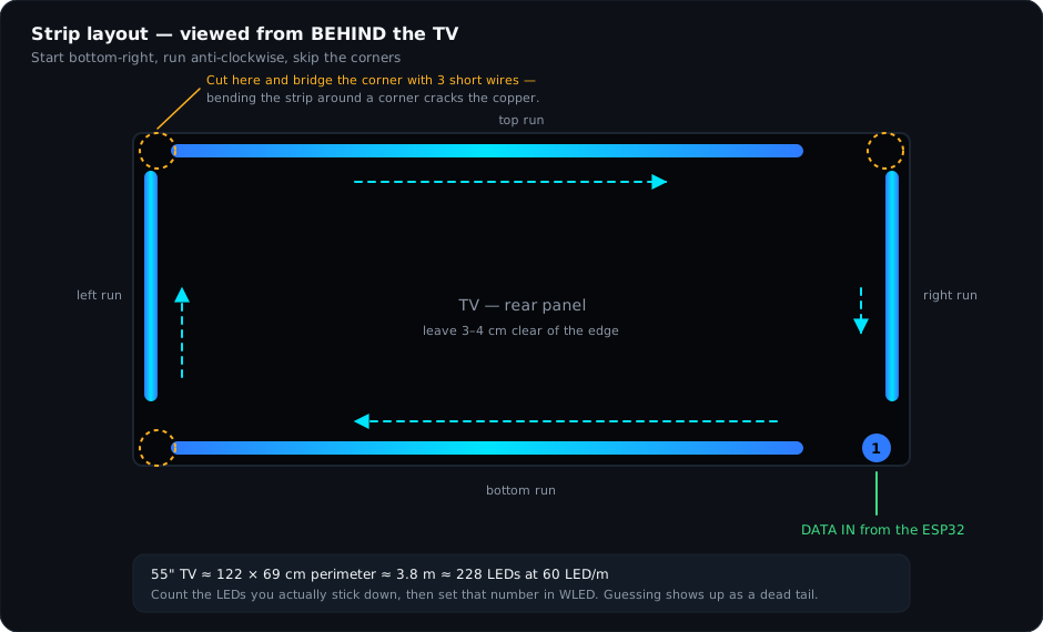
Put the TV face down on something soft, or lean it forward on its stand so you can reach the back. Run the strip around the back panel loosely, without removing the adhesive backing, and check three things: that the strip reaches all the way around, that the data end sits near your power socket, and that you have 3–4 cm of clearance from the edge of the panel so the light bounces off the wall instead of leaking around the front.
2. Count your LEDs, then cut
Almost nobody uses all 300. Run the strip around, mark where it meets the start, and cut at the nearest cut line before that mark — the copper pad with the little scissors icon. Cut through the middle of the pad so both halves keep copper. Then count exactly how many LEDs you have left. At 60 LEDs/m that is 60 per metre, six per 10 cm; measure the length you stuck down and multiply. Write the number down. You need it in step 5.
| TV size | Perimeter | LEDs at 60/m |
|---|---|---|
| 32" | ≈ 2.2 m | ≈ 132 |
| 43" | ≈ 3.0 m | ≈ 180 |
| 50" | ≈ 3.4 m | ≈ 204 |
| 55" | ≈ 3.8 m | ≈ 228 |
| 65" | ≈ 4.4 m | ≈ 264 |
| 75" | ≈ 5.1 m | ≈ 300 (the full roll) |
3. Stick it down
Clean the back panel
Wipe where the strip will go with a dry microfibre cloth, then with a little isopropyl alcohol if you have it. TV backs collect a surprising amount of dust and 3M adhesive will not hold through it.
Peel and press in sections
Peel about 30 cm of backing at a time and press the strip down as you go. Do not peel the whole run first — it will fold onto itself and the adhesive is done once it does.
Stop at every corner
Do not bend the strip around a corner. Cut it at the pad, and bridge the gap with the pre-made corner connector or the three short wires. Bending cracks the copper trace and you will lose the whole run after that point, usually a week later.
Add the 3M clips
Put a clip every 40–50 cm, especially at the top run. The adhesive holds fine at room temperature; it gets lazy in a Mumbai summer with a warm panel behind it. The clips are what stops your top run drooping in May.
4. Plug it in
Push the JST connector from the strip onto the matching lead from the ESP32 — it only goes one way. Plug the barrel connector of the 5 V 4 A adapter into the controller, then plug the adapter into the wall. The LEDs will flash briefly and then settle into a default effect. If nothing happens at all, jump to the troubleshooting guide; if the first few LEDs light and the rest do not, your LED count is set higher than what you connected, which step 5 fixes.
5. Join it to your Wi-Fi
Find the WLED hotspot
On your phone, open Wi-Fi settings and look for a network called WLED-AP. Join it. The password is wled1234.
Open the control page
Most phones will pop the captive-portal page open by themselves. If not, open a browser and go to 4.3.2.1 — that is WLED's setup address while it is running its own hotspot.
Enter your home Wi-Fi
Go to Config → WiFi Setup. Type your network name and password exactly — it is case sensitive. Give the device a name while you are there, like "tv-ambilight". Save. The ESP32 reboots and joins your network, and WLED-AP disappears.
Find it again on your network
Rejoin your normal Wi-Fi and open http://wled-tv-ambilight.local in a browser, or install the free WLED app (iOS and Android), which discovers it automatically. If neither finds it, open your router's client list and use the IP directly.
6. Tell WLED how many LEDs you actually have
This is the step everybody skips and then writes to me about. Open Config → LED Preferences and set the LED count to the number you counted in step 2. While you are on that page, confirm these — they should already be set, but check:
- LED count
- Your real number, from step 2
- Data GPIO
- 16
- Colour order
- GRB
- Max current
- 3800 mA
- Auto-calculate brightness limiter
- On
- LED type
- WS281x
Save. The strip will re-initialise and the dead tail — if you had one — disappears.
7. Turn on realtime sync
If you want the lights to follow what is on your screen, WLED has to accept realtime data from your PC. Go to Config → Sync Interfaces and make sure the realtime receivers are enabled — DDP, and E1.31 (sACN) if your software prefers it. Note the IP address shown at the top of the page; SignalRGB will ask for it.
That is the hardware done. Everything from here is software: pick effects in the WLED app, or go set up screen sync.