DIY build: flash WLED, wire it properly, solder it once
Flash the ESP32 from a browser, wire 5 V, ground and data with the protection components that actually matter, and make joints that survive.
Give this an evening. Two to three hours for a first build, most of it spent being careful rather than being slow. Read it end to end before you plug anything in — the order matters, and step 4 will tell you to do something you will be tempted to skip.
Before you start: safety, briefly
- The iron reaches 350 °C. It does not look hot. It goes in the stand every single time you put it down — not on the desk, not on the box.
- Wear the glasses. Solder spits when flux boils, and it spits upward.
- Work somewhere ventilated. Rosin flux smoke is an irritant; do not lean over it and breathe it in.
- The gloves are for handling the strip and the iron barrel while hot, not for soldering in. Do not solder wearing gloves — you lose the feel and you will burn through them.
- Unplug the 5 V adapter from the wall whenever you are soldering anything connected to it.
1. Flash WLED onto the ESP32
No IDE. No toolchain. WLED installs straight from a web page using WebSerial, which means you need Chrome or Edge on a desktop — Safari and Firefox do not implement WebSerial and the button will simply not work.
Plug the board in with the USB DATA cable
Use the cable in the box. Many USB cables are charge-only and carry no data lines; if your computer makes no sound and the board never appears, that is almost always the cause.
Open install.wled.me in Chrome or Edge
Click Install, then choose ESP32 when it asks for a board type.
Pick the serial port
A browser dialog lists serial ports. On macOS look for something like /dev/cu.usbserial or /dev/cu.SLAB_USBtoUART; on Windows look for a COM port. Select it and click Connect.
Let it write, then set up Wi-Fi
Flashing takes a minute or two. When it finishes, the installer offers to configure Wi-Fi over the same connection — do it there, it saves you the hotspot dance later.
2. Understand the wiring before you make it
Three connections: 5 V, ground, and data. The two components in the bag are not optional extras — each one prevents a specific failure that is annoying to diagnose after the strip is glued to a TV.
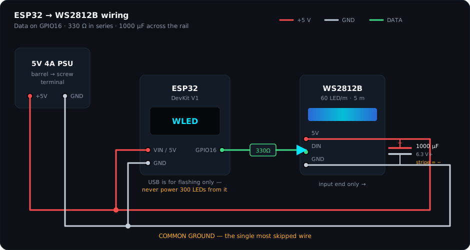
| Connection | From | To | Why |
|---|---|---|---|
| +5 V | PSU + | Strip 5 V pad AND ESP32 VIN | The strip draws amps. The ESP32 draws milliamps. Both come from the PSU, not from each other. |
| Ground | PSU − | Strip GND pad AND ESP32 GND | Common ground. Without it the data signal has no reference and the strip does nothing or goes berserk. |
| Data | ESP32 GPIO16 | Strip DIN pad, through 330 Ω | The resistor damps the signal edge and kills the reflection that shows up as random flicker. |
| Smoothing | 1000 µF across 5 V / GND | Near the strip input | Absorbs the inrush when 300 LEDs change brightness at once. Prevents stutter and a dead first LED at power-on. |
3. Cut the strip to your TV
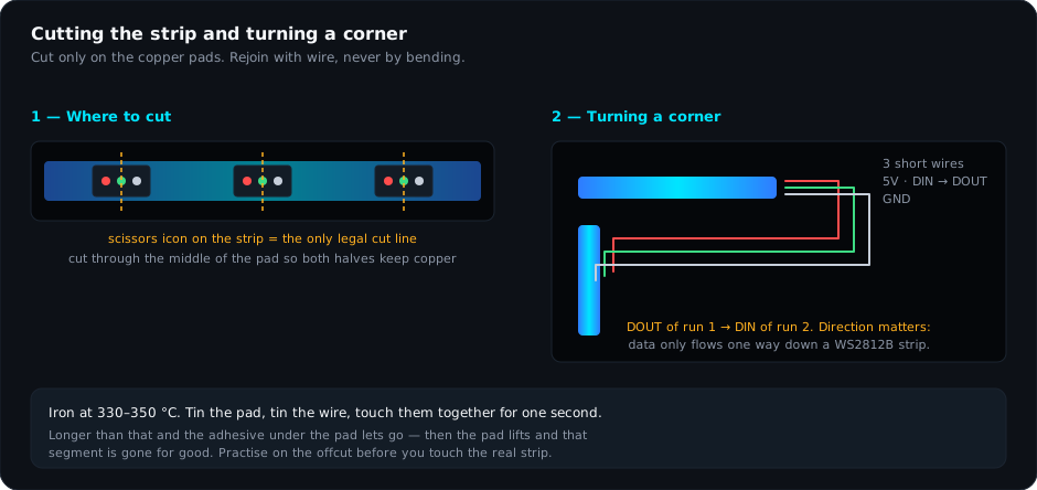
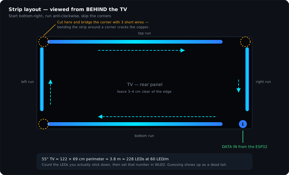
Lay the strip around the back of the TV without peeling anything, mark your finish point, and cut at the nearest pad before it. Then count the LEDs you will actually use — you will need the number for WLED.
4. Solder
Set the iron to 330–350 °C and let it come up to temperature properly — a cold iron is what makes people press harder and lift pads. Then, for every joint, the same four moves:
Tin the pad
Touch the iron to the copper pad for a second, feed a little solder onto the pad, remove. You want a small shiny dome, not a blob.
Tin the wire
Strip 3–4 mm, twist the strands, heat them and let solder wick in until the end is silver and stiff.
Join them
Hold the tinned wire on the tinned pad, touch the iron to both for about one second. The two tinned surfaces flow together. Remove the iron before you remove the wire, and do not move the wire while it cools.
Inspect
A good joint is shiny and slightly concave. A dull, grainy, ball-shaped joint is a cold joint — reheat it with a touch of flux until it flows. Cold joints work on the bench and fail in the wall.
Solder in this order: the three wires to the strip input first (they are the fiddliest and you want a fresh, steady hand), then the resistor into the data line, then the capacitor across the rail, then the ESP32 pins last. Use the JST connectors between the controller and the strip so you can unplug the TV from the controller without desoldering anything.
5. Bridge the corners
Each corner is three short wires: 5 V to 5 V, GND to GND, and — the one that matters — DOUT of the run that arrives to DIN of the run that leaves. Data only travels one way. If you wire DOUT to DOUT the run after that corner stays dark and everything before it works fine, which is a genuinely confusing way to spend an hour.
6. Power up — carefully
Check before you plug in
Look at the capacitor stripe again. Confirm 5 V is not touching ground anywhere. Confirm the data wire is on GPIO16 and not on a 5 V pin.
Power on and watch the first LED
Plug the adapter into the wall. The strip should flash and settle. If the first LED glows white and nothing else happens, power off immediately — that is usually data on the wrong pin or a missing ground.
Feel the ESP32 and the capacitor
After ten seconds, both should be cool or barely warm. Anything hot means power off, now, and re-check polarity.
7. Configure WLED
Open the device in a browser or the WLED app, then Config → LED Preferences:
- LED count
- The number you counted in step 3
- Data GPIO
- 16
- Colour order
- GRB (WS2812B is green-first)
- LED type
- WS281x
- Max current
- 3800 mA — below the 4 A adapter rating
- Auto-calculate brightness limiter
- On
Then Config → Sync Interfaces, enable the realtime receivers (DDP, and E1.31 if your software wants it), and set the realtime timeout to about 2500 ms. Note the IP address — the SignalRGB guide needs it.